Gaurav Mishra Stony Brook University

HW4 Part 2 - 3D printing the Mouse Model

The task at hand was to use use the 3d model we created in the previous assignment and 3D print it.

Parameters Used for Printing

  • temperature - 80 degree and 210 degree
  • Infill - 10%
  • Resolution - Low
  • No raft / Support required for the model

Results

Following is how the 3d printed model looks.

The source file for the above model can be found here

Remarks

  • Due to the low resolution setting used while printing the surface was not smooth.
  • Due to some issue while exporting the model some details like fillets on all corners and one extrude didnt show up in the 3d printed model.

HW4 Part 1 - Design a Mouse

The task at hand was to use FreeCAD to desing 3d model of a mouse and render a photorealistic image of the model using blender.

The sketch

Fig.1 - Rough sketch of top view of mouse

3D model

Following is how the 3d Model looked in FreeCAD.

The source file for the above model can be found here

Photorealistic Renderings

Following are couple of renderings done for the above model in Blender.

Fig.2- Rendering of the model

HW3 Part 2 - Final Box

Continuing on the previous assingment where we desingned our box for aurduino this time we were able to laser cut our plans and make the actual box.

The Cutting Plan

The final cutting plan that we used can be found here

cardboard post Laser cutting

Fig.2 - Post laser cutting

Final Box

Fig.3 - Final Box with arduino inside

Source file

Source file can be found here

HW3 - Design Box for Arduino

Design Decisions

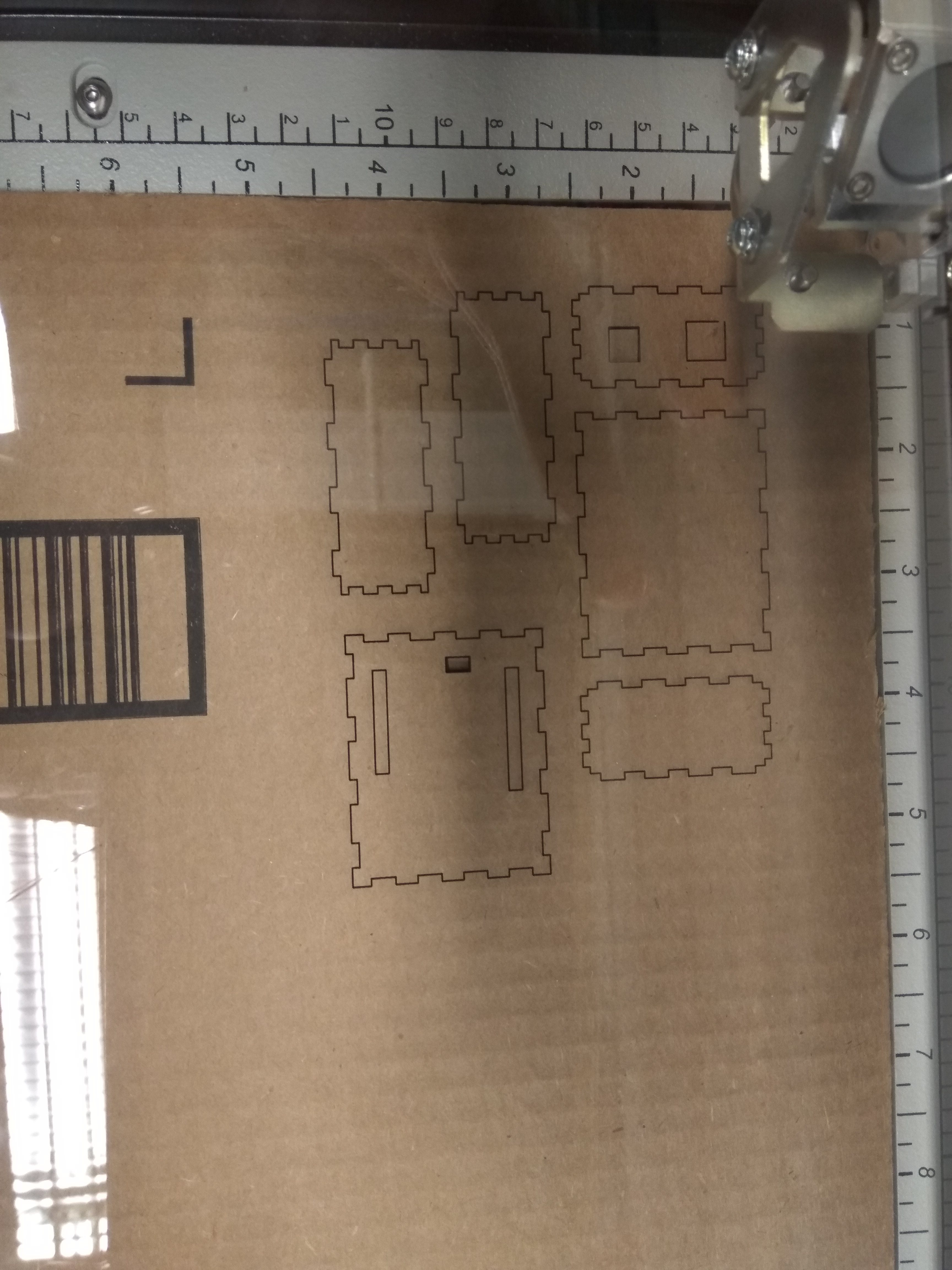
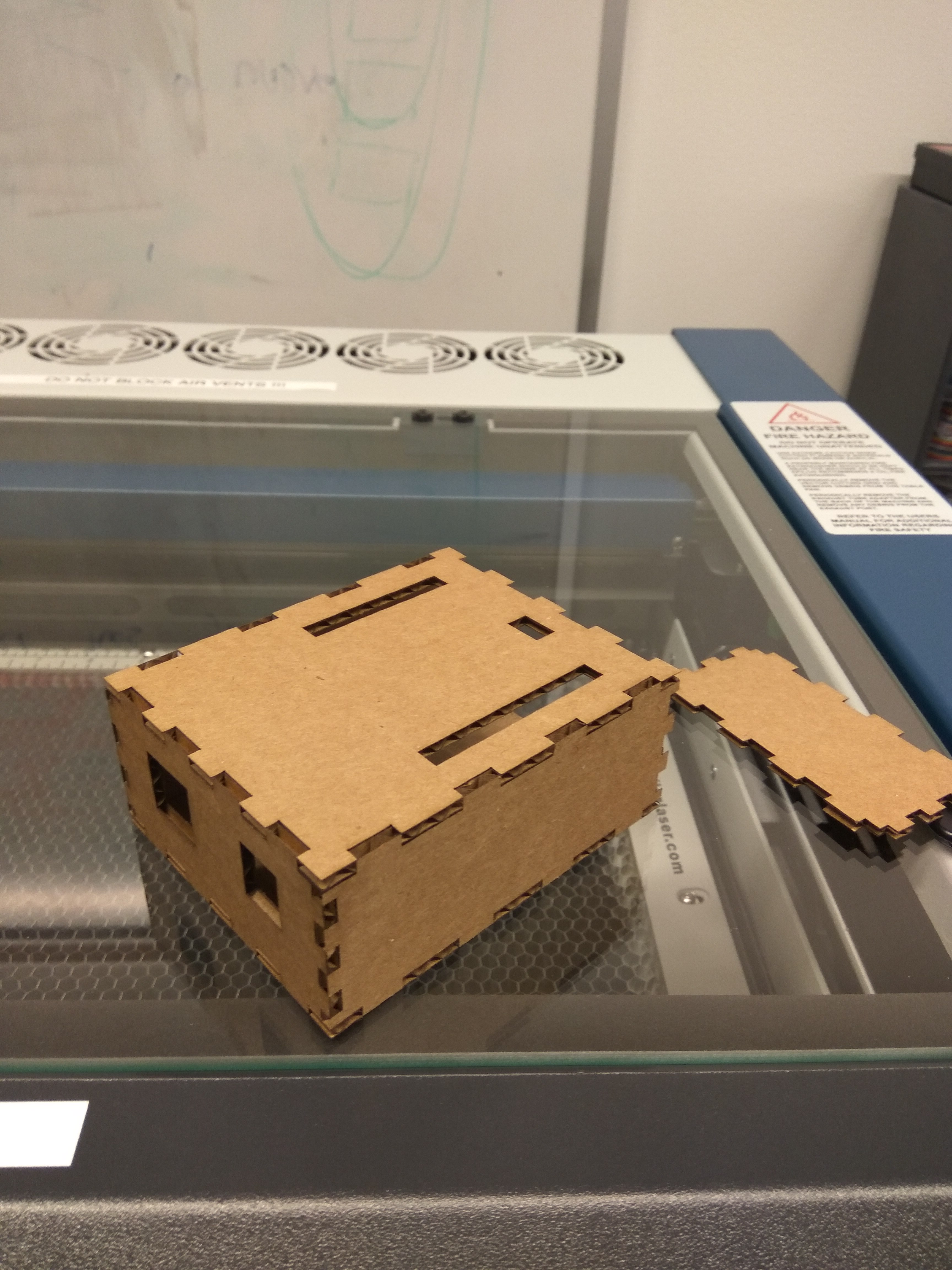
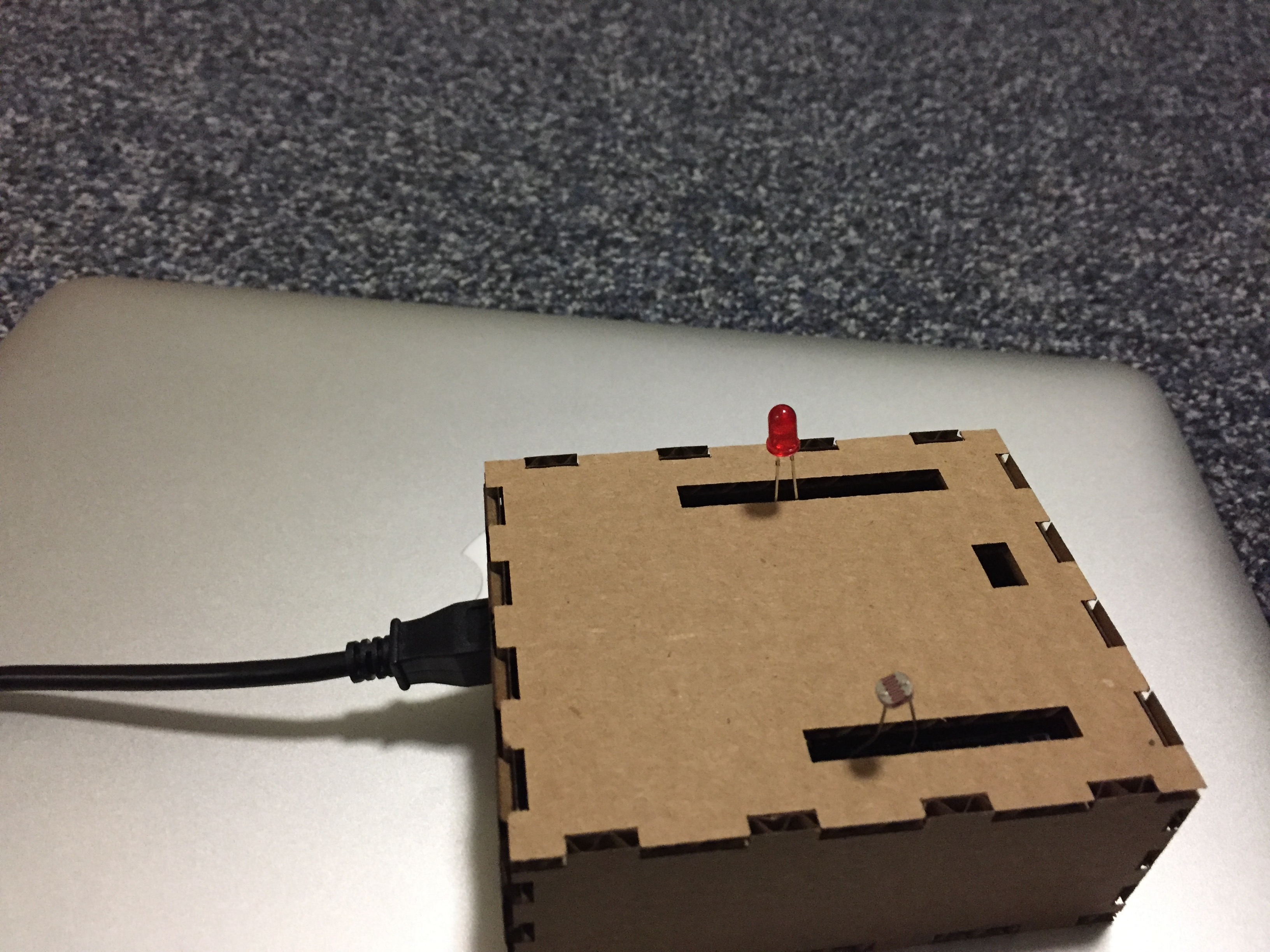
1) For supporting adding of sensors / Leds the top panel has holes made into it. These holes exposes all the GPIO pins present on Arduino.

2) Also the left panel has holes to allow inserting USB and power cables.

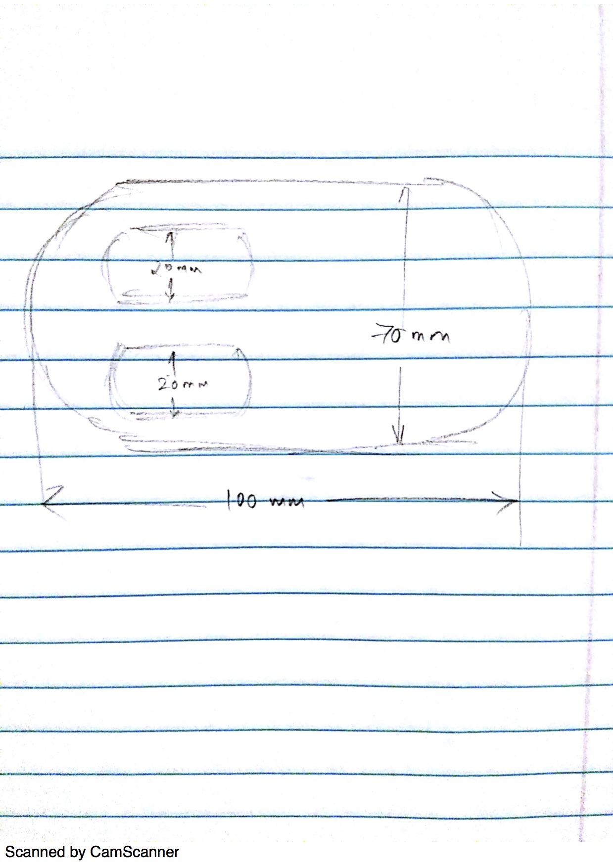
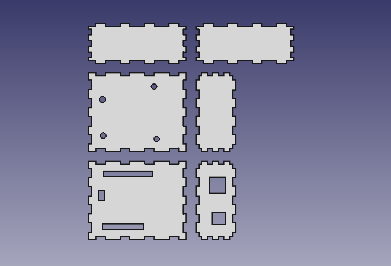
3) The dimention of the box have been kept 1 cm bigger on all sides to keep the design of finger tabs simple. ie Due to this padding the box doesnt have any weak points from where it can break easily. In absense of this padding the material would have become too thin at certain places after we cut the holes explained in above two points. This also means that the arduino will be slighly elavated from the bottom panel.

4) The arduino will have to be screwed on the bottom panel to keep it fixed in a place. The bottom panel has slots for these screws.

5) Kerfs have been taken care while designing the finger tabs. While at other places the 1 cm padding takes care of the kerfs. so even if some holes are cut extra by say 0.2 mm it wont hurt our box since all these holes are meant to allow items/cables of lesser dimentions.
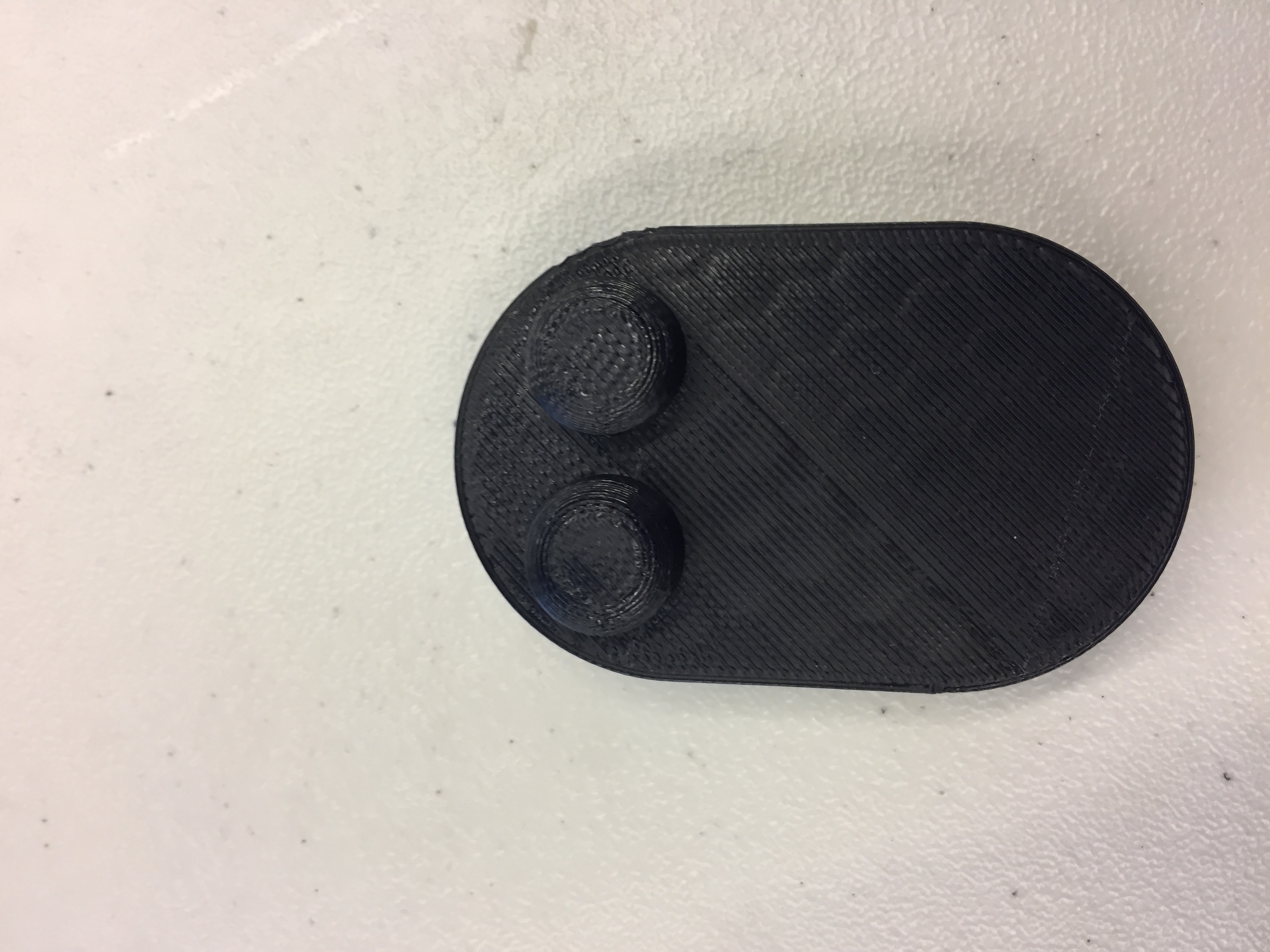
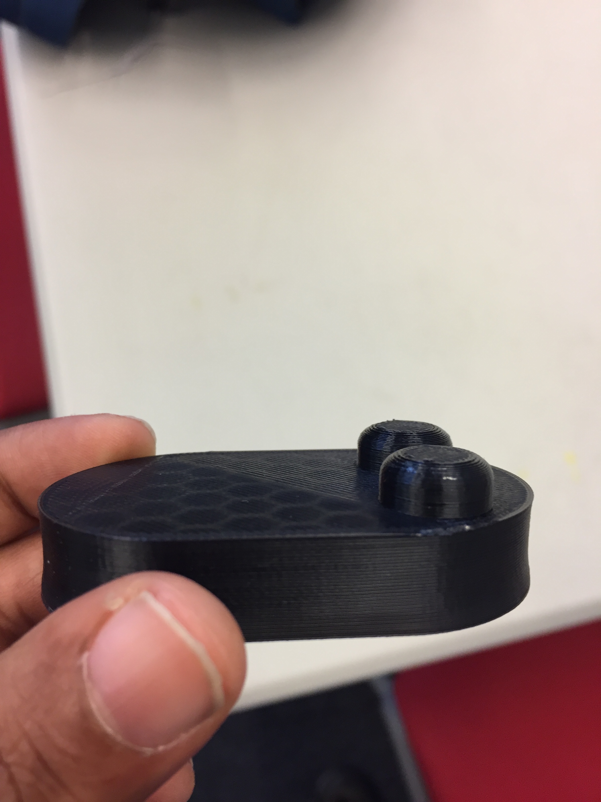
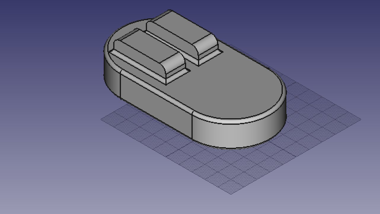
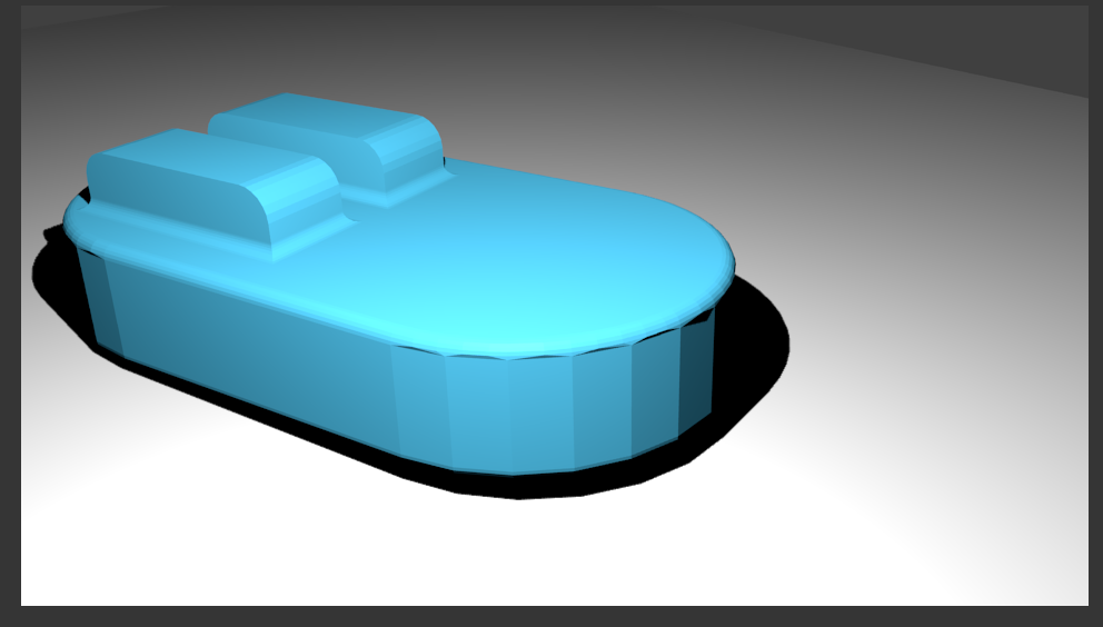
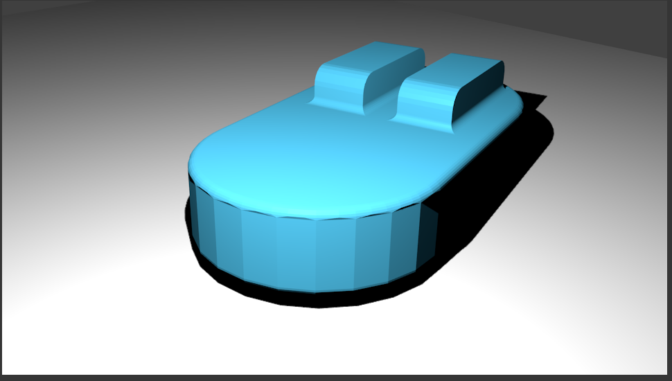
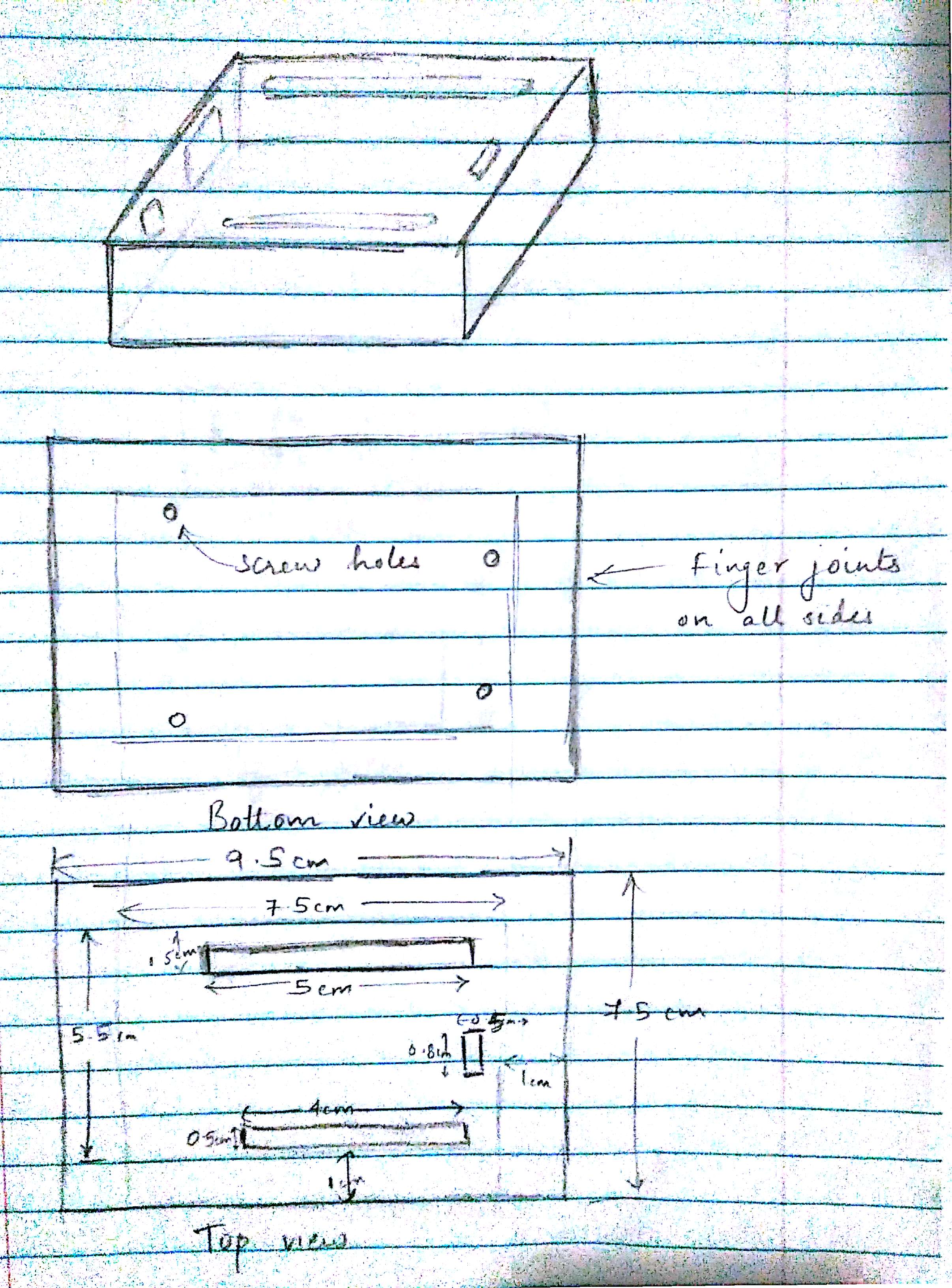
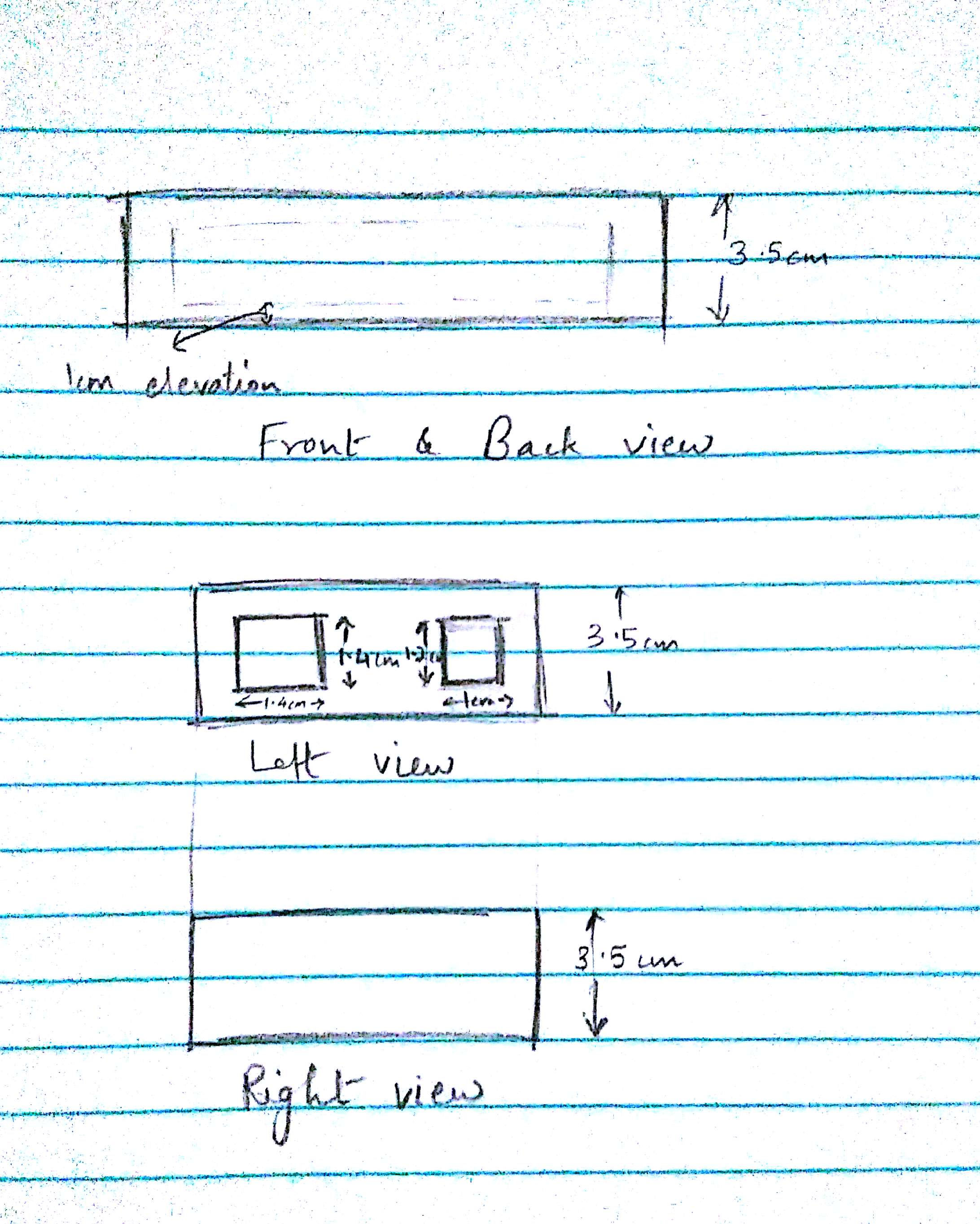
Sketches

Fig.1 - Top and bottom views
Fig.2 - front/back and left/right views

Digital Design

Fig.3 - Cut plan for the box

Source file

Source file can be found here

HW2 - Photo Sensor

Reading Data From Photo Sensor

  • Circuit Diagram can be found here

  • Code for reading from sensor and powering a LED here